Architecture (4.x version)
Introduction
This part deals with the description of the Code_TYMPAN architecture. Each section represents a part of the code and describes how it is organized:
main organization of the code and the different parts
some dependencies between these different parts
what kind of objects you will find in the different part
Description
Code_TYMPAN is made of different parts:
core&tools
graphical user interface
business logic
geometric libraries
solvers
An API in Python is used to communicate between the Graphical User Interface (GUI) and the solvers.
Three classes of users may interact differently with Code_TYMPAN:
The basic user will use the GUI which builds the data models and run a calculation through the API
The advanced user may drop the GUI and runs a build the model/run the calculation with the API
At least, the programer will add new solvers/features on the C++ solver part and the API part
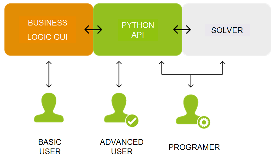
Parts separation in the 4.x architecture and how different users interact with Code_TYMPAN
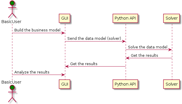
Sequence example for a basic user
If we have a look on the source directories (folders) of the differents parts, the main relations in the current architecture are:
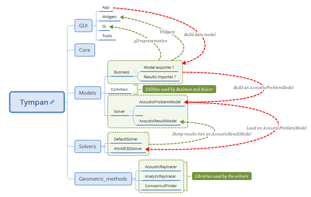
Current architecture schema
Here a second graph about the splitting between site elements (business logic) and the computation (solvers). It separates the business logic related to a site with the way to solve the acoustic problem (tympan::AcousticProblemModel). This solver data model, which can be used by any solver, is built from the Python subprocess by going through the current site and extracting relevant data: a computation needs triangles with materials from a site triangulation, acoustic sources/receptors and an altimetry.
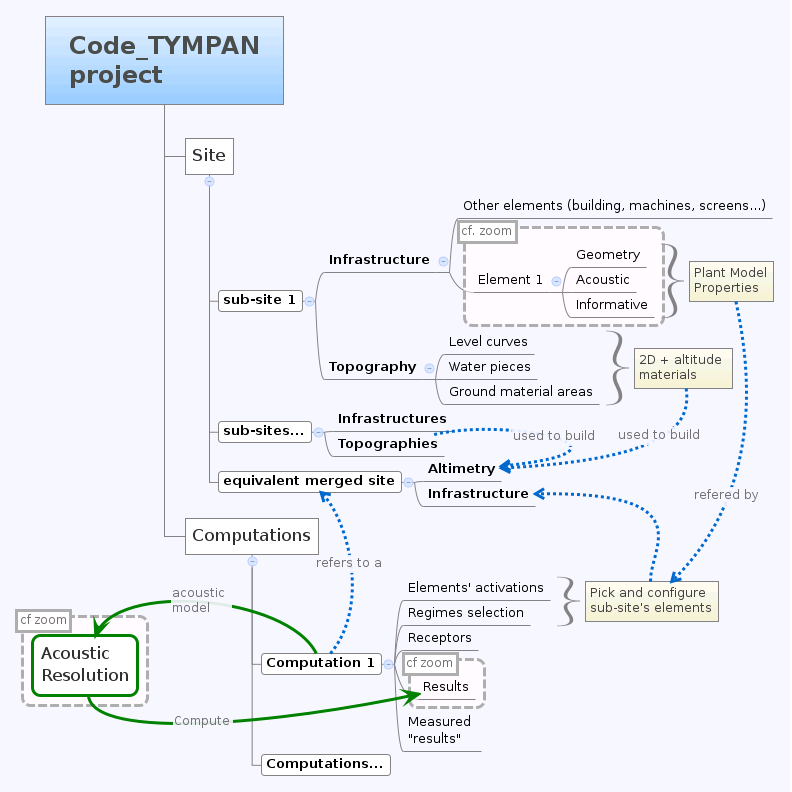
Target architecture schema
- At the Tympan sources root, we find five directories:
core: Several tools classesmodels: Data model for solvers and business logicgui: Graphical User Interfacegeometric_methods: Geometric methodssolvers: Solvers
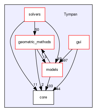
Main directories and dependencies
As several dependency graphs will be used below, we explain how it should be read:
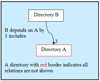
Doxygen rules for dependency graph
Core and Tools
See the core and gui/tools directories and some sub-directories in models directories:
models/business: the main base class TYElement used for every business logic objects. Also implements an interface for the solvers and some XML tools in order to export/import a Code_TYMPAN study ;
models/common: common objects used by the Business Logic objects: point, vector, matrix, etc.
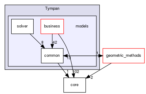
models directories and dependencies
The rationale behind the creation of models/common is to provide
basic representations and utilities which do not depend upon
TYElement nor OPrototype. Typically such representations and
utilities are likely to be shared between the main application and the
solvers.
The way the CGAL library is used deserves a special explanation. CGAL is a very powerful but quite complex templates-based library. As such dependency to CGAL appears in the headers of the client code and this has a heavy impact on compilation time and apparent code complexity.
In order to mitigate those drawbacks while benefiting from the CGAL features a variant of the classical Bridge* design pattern is used (For design pattern the key reference is [DPGoF] ).
Namely the cgal_tools module in models/common builds some
high-level functionality (constrained triangulations and domain
meshing) upon CGAL features ; its API relies on CGAL types and does
not depend on other Tympan types.
The cgal_bridge module in models/business exposes interfaces
to those features expressed with the main Tympan datatypes and ensures
the conversions.
This allows independent development and testing and reduces compilation times by breaking header dependencies propagation thanks to the bridge between the interfaces seen by the client code and the implementation.
- DPGoF
Design Patterns E. Gamma, R. Helm, R. Johnson, J. Vlissides - Adisson-Wesley
Models data
See the different sub-directories in models:
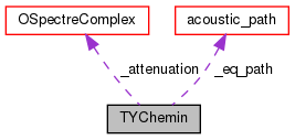
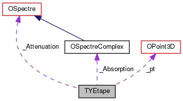
business: objects which describe a site, acoustic objects (sources, receptor, paths), materials, machines, etc.
solver: the current work which describes a data model for the solvers.
Business Logic
Note
Business Logic is the part of the code which is not technical. Deal with “real life” models: buildings, machine, fields, etc.
Code_TYMPAN offers a way to build the business objects from
a string representing their class name. This feature (mostly used during XML
deserialization) is implemented in the OPrototype class through a factory
pattern. To use this facility, it is first necessary to register all the objects
that will need it. This is handled by the init_registry() method
(from models/business/init_registry.h), that must be
ran before any call to the methods specified by OPrototype interface.
For now, the splitting between the business logic objects and the Graphical User
Interface is not clear. In other words, you can have a strong dependency
between models/business and graphical widgets described in
gui/widgets. One of the objectives described in the section is to split these parts.
Solvers
It makes a dedicated data model for the solver part (see class tympan::AcousticProblemModel), i.e. create elementary objects (as opposed to business objects) such as acoustic sources and receptors, triangles related to a material, spectrums, etc. in order to define a model that can be used by any solver.
Graphical User Interface
See in Tympan/gui and its four sub-directories:
tools: common tools and objects used for the GUI ;
widgets: widgets such as buttons, boxes and some widgets dedicated to a specific business logic objets such as a building, a field, a spectrum, etc. ;
gl: 3D representation of business logic objects such as a building, a machine, etc ;
app: GUI main classes.
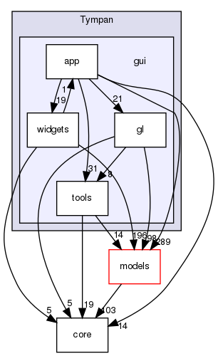
GUI directories and dependencies
App
The app package is the place where the simulation workflow is split in
order to delegate some of the processing to a Python subprocess (see launch() method
from TYCalculManager class).
When asked to perform a simulation, the computation manager:
Serializes the current project to a XML file
Calls a subprocess running
solve_project.pypython script that uses Tympan libraries to:Read the serialized file
Build a data model representing the acoustic problem
Run the simulation
Serialize the computed project (with the results)
Reads the simulation results from the file serialized by the Python subprocess
Updates the current project with these results
Rendering
The OpenGL API is used to render the scene geometry. The application uses immediate mode and
display lists, these methods are from an old specification of OpenGL and are now deprecated.
When immediate mode is used, the server (GPU) wait for the client (CPU) to send the geometry.
This method is slow because the GPU has to wait for all the data to be transferred.
The rendering function of each business logic object is located in gui/gl
and simple geometry rendering can be found at gui/tools.
In order to make the rendering faster, the OpenGL commands can be compiled and stored on the GPU. That way, the CPU simply has to tell the GPU to render this display list instead of sending the geometry on each frame. The use of displayList can be found at gui/app/TYOpenGLRenderer.cpp. It simply encapsulates all the rendering function (immediate mode) of the scene.
The modern way to render things in OpenGL relies on the use of VBO’s (Vertex Buffer Object). The idea is to store the geometry on the GPU as compact arrays (of vertices, indices, normals, …). One advantage over the display list is that you can access these buffers and edit the data in a dynamic way, whereas display lists are static, in a sense that when the geometry changes you have to recompile/send the whole display list again.
The matrix management of the application relies on the OpenGL matrices, by using functions such as glRotate(), glTranslate(), … Additionally, the matrix management of OpenGL features a stack of matrices (glPushMatrix(), glPopMatrix()). The goal of OpenGL is to take advantages of the “GPU”, but all the functions that implies matrix operations are done on the “CPU”, they are now deprecated and should be done by the application itself and not the OpenGL API. There exist many libraries that feature matrix management (CGAL? Qt?).
Picking
The picking is entirely done on the GPU by using a name stack and a selection buffer. This method relies on OpenGL deprecated functions and the steps are as follows:
We define a small “picking window”(5 pixel width) and we enter selection mode (a mode where the resulting rendering won’t be displayed).
We give a “name” (an integer) to each object we are willing to pick/draw.
The objects are then rendered. If a primitive falls inside the “picking window”, a “hit” occurs.
For each “hit”, the primitive with the smallest z-value (the closest one) is chosen.
The algorithm is located in the gui/app/TYElementPicker.cpp file.
Note
Actually, numerous names can be given to a primitive, that’s the reason why a stack is used. It enables the programmer to pick objects as a hierarchical structure.
There are two principal different ways of doing picking :
color picking ;
ray intersection.
The color picking uses entirely the GPU once again. We render every objects with an unique color, then we read the color of the pixel under the mouse. This technique is straightforward and should be simple to implement, however we can’t get the coordinate of the intersection point.
The other method consists of a ray that we cast on the scene, and then perform ray-intersection test against the object of our scene. Usually, the ray go through an acceleration structure (e.g. grid, octree, k-d tree, etc), before being tested with the bounding box of the object. This method usually run on the CPU and is independant of the rendering API. It is easy to know the exact intersection point between our ray and the picked object.
Note
It might be possible to re-use the acceleration structures from models/geometric_methods/AcousticRaytracer/Accelerator for the ray-intersection method.
Geometric libraries
Three librairies are located inside the directory geometric_methods :
AnalyticRayTracerLibrary used by ANIME3DSolver only
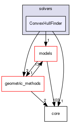
ConvexHullFinderLibrary used by the default solver only
AcousticRaytracerLibrary used mainly by ANIME3DSolver (Only few methods used by the default solver for altimetry computation)
The last library is now completely independant from Code Tympan.
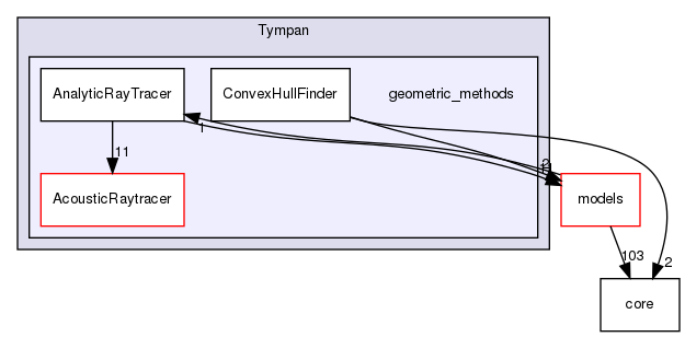
Geometric methods directories and dependencies
AnalyticRayTracer
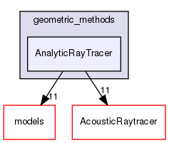
Dependencies
The collaboration graph [legend] of the AnalyticRayTracer classes are:
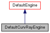
DefaultCurvRayEngine class
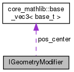
IGeometryModifier class
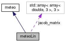
meteoLin class
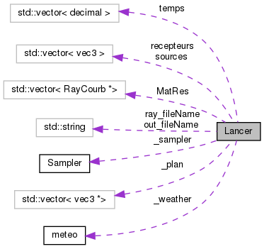
Lancer class
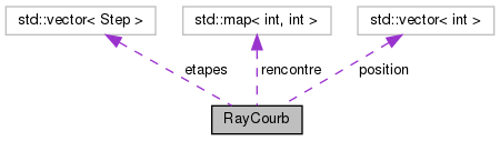
RayCourb class
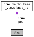
Step class
AcousticRaytracer
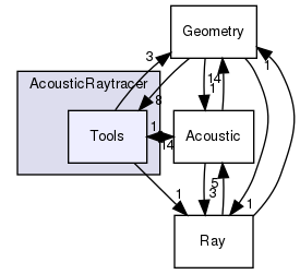
Dependencies
As AcousticRaytracer is now an independant geometric library for ray tracing, it is interesting to detail some of its classes. Here is the hierarchy of some of the mains classes of the library [legend]:
First, the Base classes which gather a lot of objects which constitutes the scene:
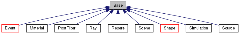
Base classes
The Sampler classes deal with the ray generators:
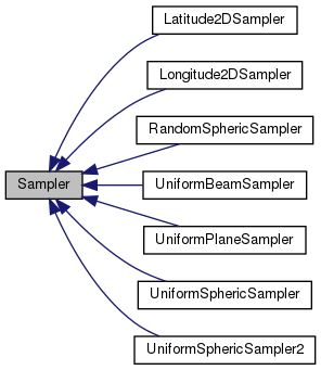
Samplers
The Engine classes is for the different ways to run the ray tracing method (sequential, parallel, …):
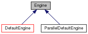
Engines
The Accelerator classes are used to select an efficient method for primitives classification:
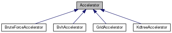
Accelerators
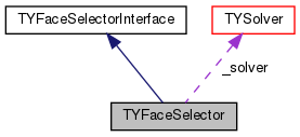
The Selector classes offers different criterias to keep or disable rays during tracing:
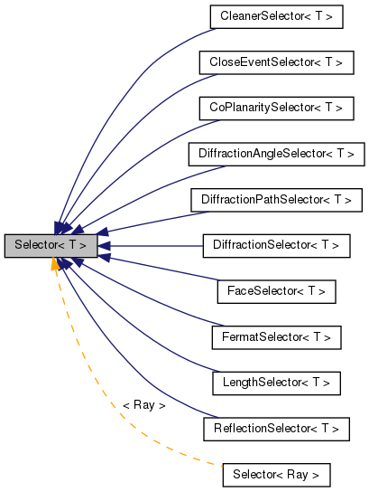
Selectors
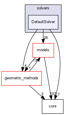
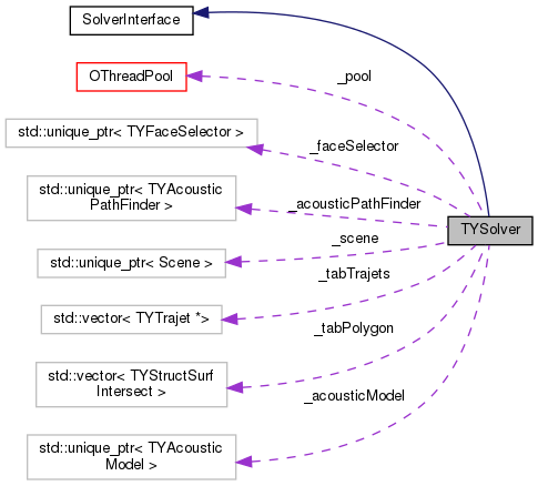
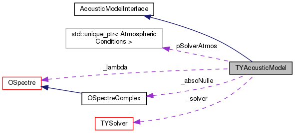
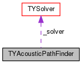
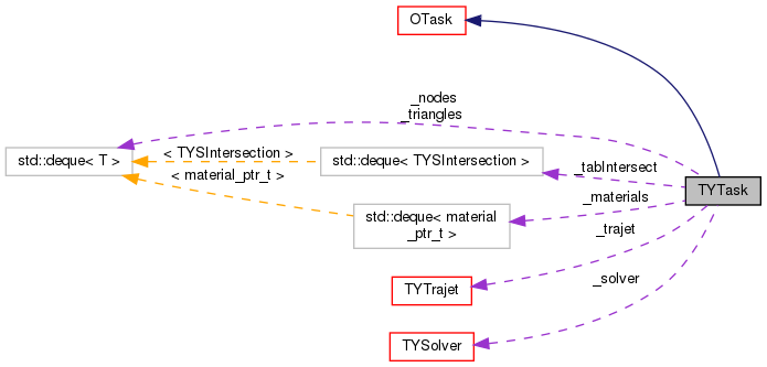
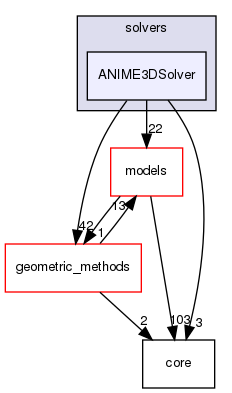
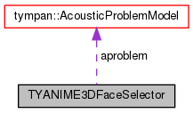
Solvers
- All directories in
solvers: DefaultSolverDefault solver using convex hull methodANIME3DSolverSolver using 3D ray tracing
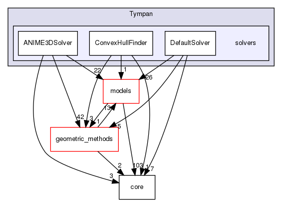
Solvers directories and dependencies
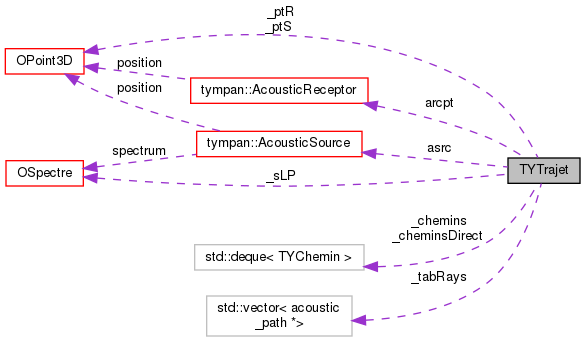
Call graphs for Tympan solvers
First, it should be noticed than in the following Doxygen the order of calls graphs is NOT always from the top to the bottom.
The complete call graph for the default solver can be find here .
A simplified call graph is (click to enlarge):
Default solver call graph
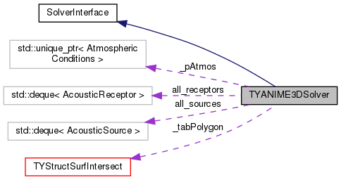
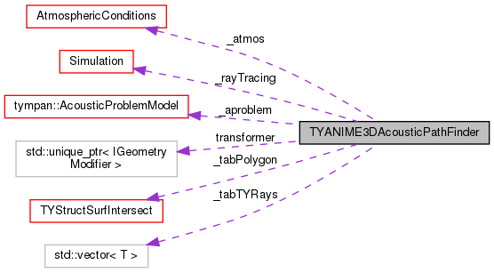
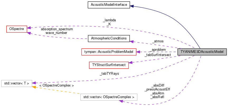
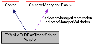
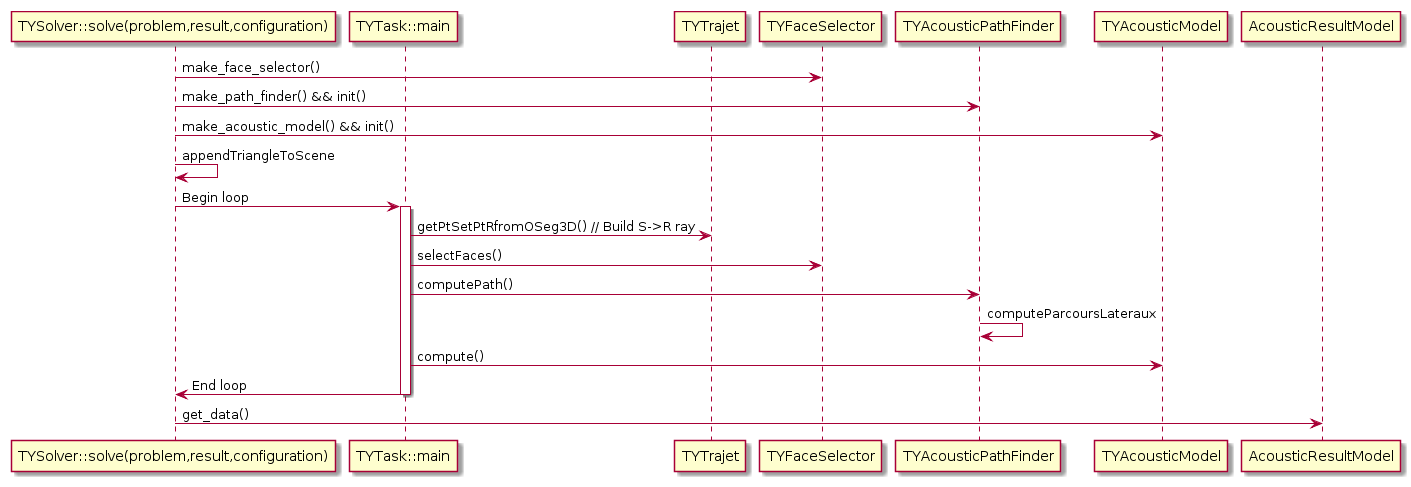
For the ANIME3D solver, the complete call graph is there . A simplified call graph is (click to enlarge):
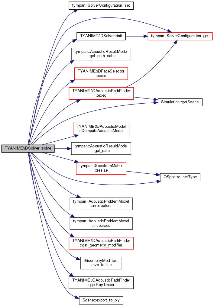
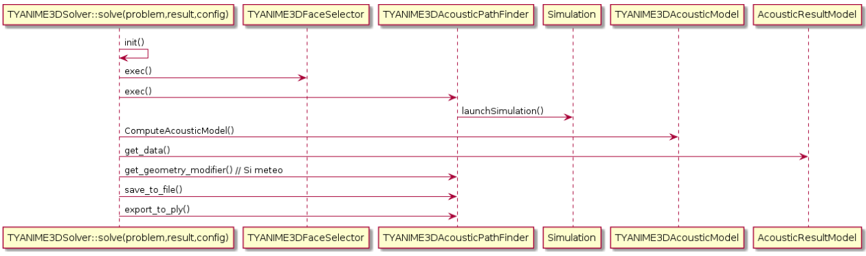
ANIME3D solver call graph
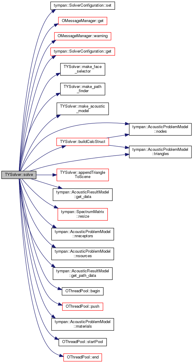
Python call graph to C++ solver TYANIME3DSolver (click to enlarge):
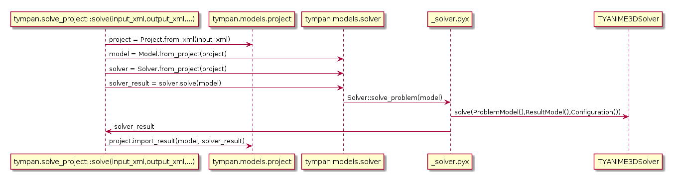
Python call graph